|
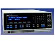
The model 1260A Impedance/Gain-Phase Analyzer is - without doubt - the most powerful, accurate and flexible Frequency Response Analyzer available today. In daily use by leading researchers wherever measurement integrity and experimental reliability are of paramount importance, the 1260A’s solid reputation is frequently endorsed in published research papers in fields such as:
- Corrosion studies
- Battery research and fuel cells
- Solar cells
- LCD's
- Bio-materials
- Ceramics / composites
- Electronic component development
- Civil engineering
One of Solartron Analytical’s extensive range of precision products designed to provide cost effective solutions for DC and AC analysis in electrochemical and materials research, the 1260A offers an outstanding measurement specification for impedance spectroscopy.
Wide frequency range
Spanning 10µHz to 32MHz with 0.015ppm resolution, the 1260A provides excellent coverage for virtually all chemical and molecular mechanisms - all in a single instrument.
Unbeatable accuracy
With an accuracy of 0.1%, 0.1º, measurements can be made with complete confidence, and even the most subtle changes in sample behavior detected and quantized
Noise free analysis
The 1260A uses Solartron Analytical’s patented single-sine correlation technique, which inherently removes the noise and harmonic distortion which plagues lesser instruments.
- Frequency resolution: 1 in 65 million (0.015ppm)
- 0.1%, 0.1º accuracy - unsurpassed by any similar instrument
- Resolution to 0.001dB, 0.01º - capturing every detail
- Measures impedances >100M?
- 2-, 3- and 4-terminal measurement configurations
- Polarization voltage up to ±40.95V
- Compatible with the renowned ZPlot software package to simplify experiments and optimize throughput.
Systems
When combined with other products from Solartron Analytical’s range, including well-proven application software (ZPlot or SMaRT), the 1260A can form the heart of an advanced electrochemical and materials measurement system, to provide superb accuracy, flexibility and reliability - even for the most complex research problems.
Impedance measurement
Virtually every liquid and solid is able to pass current when a voltage is applied to it. If a variable (ac) voltage is applied to the material, the ratio of voltage to current is known as the impedance. The measured impedance varies with the frequency of the applied voltage in a way that is related to the properties of the liquid or solid. This may be due to the physical structure of the material, to chemical processes within it or a combination of both. The advantages of impedance measurement over other techniques include:-
- Rapid acquisition of data
- Accurate, repeatable measurements
- Non-destructive
- Highly adaptable to a wide variety of different applications
- Ability to differentiate effects due to electrodes, diffusion, mass/charge transfer by analysis over different frequency ranges
- Equivalent circuit/modeling
Specifications
| Generator |
|
| |
|
Voltage mode |
Current mode |
| |
AC Amplitude ≤10MHz |
0 to 3 V rms |
0 to 60 mA rms |
| |
>10MHz |
0 to 1 V rms |
0 to 20 mA rms |
| |
Maximum AC resolution |
5 mV |
100 µA |
| |
DC Bias Range |
±40.95 V |
±100 mA |
| |
Maximum DC resolution |
10 mV |
200 µA |
| |
Output impedance |
50 ?±1% |
>200 k? at <1 kHz |
| |
|
|
| |
Frequency range |
10 µHz to 32 MHz |
| |
Max resolution |
10 µHz |
| |
Error: |
±100 ppm |
| |
Stability |
24 hrs ±1ºC |
| |
|
±10 ppm |
| |
Sweep types |
Frequency (logarithmic or linear) |
| |
|
AC/DC voltage |
| |
|
AC/DC current |
| |
Maximum voltage hi to lo |
±46 V peak |
| |
Maximum voltage lo to ground |
±0.4 V peak |
| |
Maximum current |
±100 mA peak |
| |
Impedance lo to ground |
100 k?, <10 nF |
| |
Connector |
Single BNC, floating shield |
| |
Output disable control |
Contact closure or TTL logic 0 |
| Analyzers |
|
| 3 independent analyzers operating in parallel |
| |
|
Voltage mode (x2) |
Current mode |
| |
Ranges |
30 mV, 300 mV, 3 V |
6 µA, 60 µA, 600 µA, 6 mA, 60 mA |
| |
Maximum resolution |
1 µV |
200 pA |
| |
Full scale peak |
±5 V |
±100 mA |
| |
Inputs protected to |
±46 V |
±250 mA |
| |
Connections |
single/differential BNC |
single BNC |
| |
Shields |
floating/grounded |
- |
| |
Coupling |
DC or AC (-3dB at 1Hz) |
DC or AC (-3dB at 1 Hz) |
| |
Input impedance hi to shield |
1 M?, <35 pF |
≥600 µA range, 1 ? |
| |
Input impedance shield to ground |
10 k?, 330 pF |
<600 µA range, 50 ? |
| |
Limits of error |
|
| |
Conditions |
Ambient temperature 20±10ºC, integration time >200 ms. Data valid for one year after calibration. |
| |
|
| |
Gain-phase measurements
Applies to all ranges at >10% full scale

|
Impedance Measurements
Applies for stimulation level of 1V for impedances >50? or 20mA for impedances <50?

|
|
| Displayed Results |
|
| |
Variable |
Frequency, AC amplitude, DC bias |
| |
Measured parameters |
Voltage gain, phase, real, imaginary, Z, R, X, Y, G, B, V, I group delay, C, L, Q, D |
| Interfaces |
|
| |
GPIB (IEEE-488) |
For instrument control or for directly driving attached plotter using HPGL language |
| |
RS423 |
For directly driving attached plotter using HPGL language |
| Power Requirements |
|
| |
Voltage |
90 to 126V, 198 to 252 VAC |
| |
Frequency |
48 to 65 Hz |
| |
Power |
< 230 VA |
| Dimensions |
|
| |
Width |
432 mm (17") |
| |
Depth |
573 mm (22.56 ") |
| |
Height |
176 mm (6.93") |
| Weight |
18 kg (40 lbs) |
| Operating Temperature Range |
0 to 50ºC (32 to 122ºF) |
|
 来宝会员
来宝会员