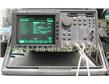
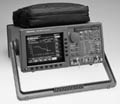
PDH/SDH网络测试仪TektronixCTS-850
- 属性
- 详情
- 产地: 美国
- 关注度: 次
- 品牌: Tektronix
- 型号: CTS-850
- 厂商性质: 生产型,贸易型,服务型,
- 价格: 电议
- 添加时间: 2011/12/8
产品介绍
PDH/SDH网络测试仪 美国泰克 CTS-850
Features and Benefits
Applications
Supports New ITU-T O.172 Conformance Test SetThe CTS850 is a versatile analyzer for Broadband Network Testing. It has a powerful, yet uncomplicated, menu structure which allows both the novice and expert user to accurately configure measurements on SDH and PDH networks very quickly. All measurement connections are conveniently located directly on the front panel close to the signal status LEDs and easy-to-read display. A field-interchangeable optical module and a floppy disk drive for retrieval of stored setups and results complete the front-panel layout to create a "field-friendly" instrument. SDH/PDH/Jitter and Wander TestingThe CTS850 creatively addresses growing concerns surrounding hybrid SDH/PDH networks in the area of timing and synchronization. Its industry-leading, DSP-based, Jitter and Wander measurement capability provides a high 300 UI jitter measurement range, handles all line rates from 2 MBps to 622 MBps through existing front-panel connectors and introduces exclusive new measurements for digital video services. The CTS850 unlocks the power of the SDH frame structure by combining bit error testing with overhead analysis and payload mapping and demapping. It provides read/write access to overhead bytes, DCC add/drop, and complete G.783 pointer test sequences. The CTS850 is optimized for installation and maintenance of both current and future SDH networks. Additional functionality, reflecting evolving standards such as new O.172, can be downloaded through the built-in disk drive. One of the CTS850's many powerful functions is error analysis and display. In addition to simple error counts and rate determination, the CTS850 makes measurements according to G.821, G.826, G.827, and new M.2101.1 performance analysis and M.2100 error analysis so that network quality of service can be fully verified in or out of service. Histograms boost the power of error analysis by enabling an easy correlation of time-critical events. Thus, time-consuming searches through long strips of error printouts are eliminated, freeing you to spend time fixing problems, not finding the cause. PDH TestingMany networks have evolved from PDH to include SDH rings and long-distance, high-capacity trunks. The PDH network segments are commonly retained for access, service delivery, and economic reasons. The CTS850 Opt. 38, PDH Tributary card provides features for testing and accessing PDH subrates from 140 MBps, 34 MBps, 8 MBps, 2 MBps, down to N/M × 64 Kbps. Additional PDH test features also include simultaneous multilayer G.826, M.2100 results, Round Trip Delay, Voice Channel Monitor, and Burst FAS Errors. This option also empowers the CTS850 with mapping and demapping of 2, 34, and 140 MBps payloads in virtual containers and testing of TU-12, TU-3 and AU-4 overheads, making it ideal for testing hybrid networks. Jitter and Wander TestingTo support current and emerging ITU-T and ETSI standards, CTS850 Opt. 14 for Jitter and Wander provides the most comprehensive, easy-to-use measurements for both SDH and PDH equipment and networks. The CTS850 is the first test set to fully conform to the requirements of the new ITU-T O.172 (Jitter/wander test for SDH networks). So for the first time, measurements of pointer jitter can be made reliably and accurately. Widely variable results are a thing of the past. With its wide-ranging and comprehensive generation, analysis, pointer movement, automated jitter output, transfer, and tolerance testing, the CTS850 is the complete solution for your current and future test requirements. Also included in Opt. 14 is Real-Time Wander Analyst application software for MTIE and TDEV parameter analysis. Now you can fully test and qualify the timing and synchronization of your new SDH/PDH equipment and networks. Jitter history histograms can be correlated with simultaneously-acquired Wander TIE data so troublesome conditions can be quickly diagnosed. Video Service Performance and 45 MBps Mapping and DemappingDigital video services demand a more stringent level of SDH/PDH timing and synchronization performance than many other services. The CTS850 Opt. 14 provides exclusive new measurements at the network interface to assess video service performance. Also, CTS850 Opt. 55, provides the ability to test 45 MBps Mapping and Demapping, including Jitter and Wander testing, to bring the CTS850's advanced benefits to Video Service Measurement. Flexible and Easy-to-Use
SDH Testing
45 MBps (DS3) Testing
PDH Testing
Jitter/Wander Testing
Conformance to ITU-T new O.172 and O.171ITU-T New O.172New O.172 provides requirements for SDH Jitter and Wander test sets and also new requirements for PDH tests, where necessary. The prime purpose of new O.172 is to improve accuracy and consistency of Jitter and Wander measurements between different units. A special focus is the accurate and reliable measurement of pointer jitter. Only test sets conforming with O.172 can provide the minimum acceptable performance level. New O.172, together with O.171, recommendations establish test-set requirements for:
ITU-T O.171 OnlyLegacy O.171 provides requirements for PDH Jitter test sets. O.171 is not sufficient for SDH tributary test. This is because pointer jitter testing has new requirements; The main limitations are:
O.171 test sets are unable to guarantee reliable and accurate pointer jitter measurements. Therefore it is important for users to ensure that test sets conform to new O.172. The Tektronix CTS850 is the first Jitter and Wander test set to meet the new requirements of ITU-T O.172 (together with O.171). CTS850 performance easily exceeds O.172 with modern DSP-based Jitter and Wander measurement technology (old analog techniques typically provide less performance). CTS850 Jitter and Wander option conforms to O.172 and O.171, specific examples include:
|
||||||||||||||||||||||||||||||||||||||||||||||||||||||||||||||||||||||||||||||||||||||||||||||||||||||||||||||||||||||||||||||||||||||||||||||||||||||||||||||||||||||||||||||||||||||||||||||||||||||||||||||||||||||||||||||||||||
SDH Generator OutputElectrical Output - Data Rates: STM-0: 51.84 MBps STM-1: 155.52 MBps Data Formats: STM-0E: B3ZS STM-1E: CMI Signal Level at Transmit Output: STM-0E: ±1.0 Vpk ±10% into 75 Ohm STM-0E: (-6 dB) STM-0E output: attenuated with 6 dB cable loss (-12.7 dB square-root f characteristic cable) STM-1E: ±0.5 Vpk ±10% into 75 Ohm STM-1E(-6 dB): STM-0E output attenuated with 6 dB cable loss (-12.7 dB square-root f characteristic cable) Pulse Shape at Transmit Output: Meets ITU-T G.703 Pulse Masks. Return Loss: >15 dB Connectors: Unbalanced BNC, 75 Ohm to ground. Opt. 11: 1.6/5.6, 75 Ohm to ground.
Optical Output - Data Rates: STM-0: 51.84 MBps STM-1: 155.52 MBps STM-4: 622.08 MBps Optical Module Options: Opt. 01: Electrical only, STM-0/1E Opt. 03: 1310 nm, IR, STM-0/1 Opt. 04: 1310 nm, IR, STM-0/1/4 Opt. 05: 1550 nm, LR, STM-0/1/4 Opt. 06: 1310/1550 nm, STM-0/1/4 Signal Level and Wavelength: 1310 nm: -10 dBm, typical (Opt. 03, 04, 06) 1550 nm: 0 dBm, typical, (Opt. 05, 06) Pulse Shape: Meets ITU-T G.957 Eye Pattern Masks. Wavelength: 1308 nm, typical (Opt. 03, 04, 06) 1550 nm, typical (Opt. 05, 06) Spectral Width: 1310 nm: <4 nm (Opt. 03, 04, 06) 1550 nm: <1 nm (Opt. 05, 06) Laser Classification: EN60825-1 (Class 1), 21CFR1000 (Class I) Connectors: User-selectable when ordering – Opt. 31: FC-PC Opt. 32: ST Opt. 33: SC Opt. 34: DIN Other connector types - consult factory |
||||||||||||||||||||||||||||||||||||||||||||||||||||||||||||||||||||||||||||||||||||||||||||||||||||||||||||||||||||||||||||||||||||||||||||||||||||||||||||||||||||||||||||||||||||||||||||||||||||||||||||||||||||||||||||||||||||
SDH Signal StructurePayload - Payload Channel (AU): Concatenated VC4-4c signal in STM-4 One active AU-3 in STM-0 One active AU-4 in STM-1 One active AU-4 in STM-4 (other 3 channels unequipped)
Unequipped Payload - C2 byte is set to 00. Bulk fill set to 00. |
||||||||||||||||||||||||||||||||||||||||||||||||||||||||||||||||||||||||||||||||||||||||||||||||||||||||||||||||||||||||||||||||||||||||||||||||||||||||||||||||||||||||||||||||||||||||||||||||||||||||||||||||||||||||||||||||||||
SDH Internal Pattern GeneratorPatterns - Bulk Fill in a selected AU channel. (AU-3 or AU-4) PRBS: 29-1, 215-1, 220-1, 223-1; All 1s, All 0s, 8-bit programmable word. PRBS patterns can be inverted.
RSOH Orderwire - E1 RSOH User Byte - F1 MSOH Orderwire - E2 POH User Byte - F2 DCC Bytes - D1-D3 DCC Bytes - D4-D12
PRBS: 215-1; 220-1; 223-1 PRBS patterns can be inverted.
Error Types and Insert Rates - Single or Continuous.
RS BIP B1 STM-0: 1.0e-3 to 1.0e-10 STM-1: 1.0e-4 to 1.0e-10 STM-4: 1.0e-5 to 1.0e-10 MS BIP B2 STM-0: 1.0e-3 to 1.0e-10 STM-1/4: 1.0e-4 to 1.0e-10 Path BIP B3 STM-0: 1.0e-3 to 1.0e-10 STM-1/4: 1.0e-4 to 1.0e-10 HP-REI G1 STM-0: 1.0e-3 to 1.0e-10 STM-1/4: 1.0e-4 to 1.0e-10 Payload (Pattern Bit Error) 1.0e-3 to 1.0e-10
Defects - LOS, LOF, LSS (Pattern Loss). RS-TIM, MS-AIS, MS-RDI, AU-LOP, AU-AIS, HP-RDI, HP-TIM, HP-PLM, HP-UNEQ, LP-RDI, LP-RFI, LP-TIM, LP-UNEQ, LP-PLM, TU-AIS. |
||||||||||||||||||||||||||||||||||||||||||||||||||||||||||||||||||||||||||||||||||||||||||||||||||||||||||||||||||||||||||||||||||||||||||||||||||||||||||||||||||||||||||||||||||||||||||||||||||||||||||||||||||||||||||||||||||||
SDH Transmitter ClockInternal Clock Accuracy - ±4.6 ppm, for instrument calibrated within 36 months External Clock Reference - Rates: 2.048 MBps ±50 ppm 2.048 MHz ±50 ppm 1.544 MBps ±50 ppm Input: Unbalanced, 75 Ohm, BNC connector G.703 signal format Recovered Clock: Loop timing Clock is recovered from received signal
Transmit Line Frequency-Offset Rate - ±100 ppm of nominal line rate Resolution: 0.1 ppm |
||||||||||||||||||||||||||||||||||||||||||||||||||||||||||||||||||||||||||||||||||||||||||||||||||||||||||||||||||||||||||||||||||||||||||||||||||||||||||||||||||||||||||||||||||||||||||||||||||||||||||||||||||||||||||||||||||||
SDH Receiver InputElectrical Input - Data Rates: STM-0: 51.84 MBps ±100 ppm STM-1: 155.52 MBps ±100 ppm Data Formats: STM-0E: B3ZS STM-1E: CMI Signal Sensitivity/Equalization: STM-0E: 0.5 Vpk min to 1.2 Vpk max STM-0E -6 dB*1: 0.25 Vpk min to 0.6 Vpk max STM-0E -12dB*2: 0.125 Vpk min to 0.35 Vpk max STM-0E Monitor: 20 dB of flat loss below -6 dB STM-1E: 0.35 Vpk min to 0.6 Vpk max STM-1E -6 dB*3: 0.35 Vpk min to 0.6 Vpk max STM-1E -12 dB*4: 0.07 Vpk min to 0.3 Vpk max STM-1E Monitor: 26 dB of flat loss below STM-1E level
*1 -6 dB cable loss at 25 MHz (-12.7 dB square-root f characteristic cable) *2 -12 dB cable loss at 25 MHz (-12.7 dB square-root f characteristic cable) *3 -6 dB cable loss at 78 MHz (-12.7 dB square-root f characteristic cable) *4 -12 dB cable loss at 78 MHz (-12.7 dB square-root f characteristic cable) Signal Level Display: Readout for: Electrical signal level in mV Return Loss: >15 dB Connectors: Unbalanced BNC, 75 Ohm to ground Opt. 12 - 1.6/5.6, 75 Ohm to ground Optical Input - Data Rates: STM-0: 51.84 MBps (±100 ppm) STM-1: 155.52 MBps (±100 ppm) STM-4: 622.08 MBps (±100 ppm) Maximum Input Power: -7 dBm: Opt. 05 and 06 include a 10 dB attenuator for use at 1550 nm Operating Wavelength: 1310 nm and 1550 nm: 1100 nm to 1570 nm operating range Signal Sensitivity: -28 dBm for BER <10-10 Optical Power Meter Accuracy: ±2 dBm, typical: For input power in a range of -30 dBm to -6 dBm. Resolution 0.1 dBm. Connectors: User-selectable when ordering – Opt. 31: FC-PC Opt. 32: ST Opt. 33: SC Opt. 34: DIN Other connector types - consult factory Through Mode: Monitors a selected channel while passing the signal through unchanged, both electrical and optical. |
||||||||||||||||||||||||||||||||||||||||||||||||||||||||||||||||||||||||||||||||||||||||||||||||||||||||||||||||||||||||||||||||||||||||||||||||||||||||||||||||||||||||||||||||||||||||||||||||||||||||||||||||||||||||||||||||||||
Section OverheadAccess - Set overhead bytes to any value from binary 00000000 to 11111111: A1, A2, J0, E1, F1, D1 to D3, D4 to D12, K1, K2, S1, M1, E2. View all Section Overhead bytes. Clear text decode of S1 message byte provided per G.707.
Add/Drop - Orderwire Access to E1 or E2 byte from RJ11 jack. Insert data from the Overhead Add/Drop connector into the Section DCC, Line DCC, E1, E2, or F1 user byte. Drops data from the Section DCC, Line DCC, E1, E2, or F1 user byte out to the Overhead Add/Drop connector. PRBS evaluation is provided internally for bytes E1, E2, F1, F2, D1 to D3, D4, to D12.
K1 and K2 (APS) - Set the APS Bytes, K1 and K2, to any code defined in ITU-G.783 Annex A and G.841. Selectable by clear text for all Span and Ring messages. |
||||||||||||||||||||||||||||||||||||||||||||||||||||||||||||||||||||||||||||||||||||||||||||||||||||||||||||||||||||||||||||||||||||||||||||||||||||||||||||||||||||||||||||||||||||||||||||||||||||||||||||||||||||||||||||||||||||
Path OverheadAccess - Set Path Overhead bytes to any value from binary 00000000 to 11111111: C2, G1 (bits 5 to 7 only), F2, H4 (bits 1 to 6 only), F3, K3, N1. View all Path Overhead bytes. Clear text decode of C2 signal label per ITU-G.707. Path Label Mismatch (PLM) and Unequipped (UNEQ) detection.
Add/Drop - Insert data from the Overhead Add/Drop connector into the F2 user byte. PRBS can be used through F2 internally.
Trace Bytes J1, J0 - J1 HP-Trace: VC4 Overhead - User-defined 15-byte with CRC, or 64-byte formats per ITU-T G.707. J0 RS-Trace: User-defined 15-byte with CRC per ITU-T G.707. |
||||||||||||||||||||||||||||||||||||||||||||||||||||||||||||||||||||||||||||||||||||||||||||||||||||||||||||||||||||||||||||||||||||||||||||||||||||||||||||||||||||||||||||||||||||||||||||||||||||||||||||||||||||||||||||||||||||
Pointer MovementSingle - Single pointer justification. Burst - Bursts of two to eight pointer justifications spaced four frames apart. All adjustments within a given burst are in the same direction. Subsequent bursts are in alternating directions. Continuous - Pointer justifications occur continuously at a predetermined rate in an incrementing, decrementing, or alternating direction. Rate between movements: 2 ms to 10 s, with a resolution of 1 ms. Set to Value - Set to a new location with or without the NDF being set. Range is 0 to 1023 (783 to 1023 are illegal locations). |
||||||||||||||||||||||||||||||||||||||||||||||||||||||||||||||||||||||||||||||||||||||||||||||||||||||||||||||||||||||||||||||||||||||||||||||||||||||||||||||||||||||||||||||||||||||||||||||||||||||||||||||||||||||||||||||||||||
Pointer Test SequencesAU and TU Pointer sequences available: G.783(a) Single Alternating G.783(b) Regular + Double G.783(c) Regular + Missing G.783(d) Double Alternating G.783(e) Single G.783(f) Burst G.783(g1) Periodic 87-3 G.783(g2) Periodic 87-3 With Add G.783(g3) Periodic 87-3 With Cancel G.783(h1) Periodic G.783(h2) Periodic with Add G.783(h3) Periodic with Cancel Phase Transient Pointer Adjustment Burst. Pointer Direction - Positive or Negative. Initialization Period - On or Off. 30-second burst of 1 pointer per second in the same direction as the selected test, per ITU-T G.783.
Cooldown Period - On or Off. This will last at least 60 seconds, for an integral number of complete sequences, per ITU-T G.783.
Combined Jitter - Simultaneous PDH mapping frequency offset with ITU-T G.783 Pointer Sequences generation. To enable the measurement of combined mapping and Pointer Jitter. |
||||||||||||||||||||||||||||||||||||||||||||||||||||||||||||||||||||||||||||||||||||||||||||||||||||||||||||||||||||||||||||||||||||||||||||||||||||||||||||||||||||||||||||||||||||||||||||||||||||||||||||||||||||||||||||||||||||
SDH MeasurementsSDH Anomalies - Error Count, Error Rate, and Errored Seconds for: B1, B2, B3, TU Path BIP, Payload, MS-REI, HP-REI, LP-REI. Network Defects (Seconds) - LOS, LSS (Pattern Loss), CTS Loss of AC Power. SDH Defects (Seconds) - RS-TIM, MS-AIS, MS-RDI, AU-AIS, AU-LOP, HP-RDI, HP-TIM, HP-UNEQ, HP-PLM, LP-RDI, LP-RFI, LP-TIM, LP-UNEQ, LP-PLM, TU-AIS. AU Pointer Measurements - NDF Sec., Illegal Sec., +Ve Just. Count, -Ve Just. Count, Illegal Count, NDF Count, Pointer Value. G.826 Error Analysis - RS B1, MS B2, Path B3, AU-LOP, AU-AIS, HP-REI, HP-TIM, HP-PLM, HP-UNEQ, LP-REI, LP-TIM, LP-UNEQ, TU-LOP, TU-AIS Seconds and ratio. Errored Blocks, ES, %ES, SES, %SES, UAS, %UAS, CSES Periods, Background Block Errors, %Background Block Error, Path UAS, %Path UAS.
G.826 Performance Analysis - Performance analysis performed as per user settable allocation percentage for SDH and PDH. Regeneration Section, Multiplex Section, high- and low-order path layers are individually evaluated. Analysis Results: Pass or Fail.
G.821 Analysis - Pattern Bit Seconds and % of total time. Error-Count, ES, DM, SES, UAS, EFS.
M.2101.1 Error Analysis - B1, B2, B3, RS-TIM, MS-REI, MS-RDI, MS-AIS, AU-AIS, AU-LOP, HP-REI, HP-TIM, HP-UNEQ, HP-PLM, HP-RDI, LP-REI, LP-TIM, LP-UNEQ, LP-PLM, LP-RDI, LOS, OOF, TU-LOM, TU-AIS, TU-LOP, TU-BIP. Errored Blocks, ES, %ES, SES, %SES, CSES, UAS, %UAS, Background Block Errors, %Background Block Error, Path UAS, %Path UAS.
M.2101.1 Performance Analysis - Test Types: BIS (Bring Into Service). PAR (Performance After Repair). MAINT (Maintenance). Custom (User Controls Performance Limits). Automated Test types allow Performance Analysis for Regeneration Section, Multiplex Section, high- and low-order path layers based upon user-settable allocation percentage. Custom test type allows the user to select the performance objective limits. Analysis Results: Acceptable, Provisional/Degraded, or Unacceptable. |
||||||||||||||||||||||||||||||||||||||||||||||||||||||||||||||||||||||||||||||||||||||||||||||||||||||||||||||||||||||||||||||||||||||||||||||||||||||||||||||||||||||||||||||||||||||||||||||||||||||||||||||||||||||||||||||||||||
SDH Standards ComplianceSDH Framing - G. 707 SDH Multiplexing - G.707 SDH Optical Interfaces - G.957 SDH Electrical Interfaces - G.703 SDH Jitter Tolerance - G.825, G.958, O.172 SDH Pointer Sequences - G.783 SDH Error Analysis - G.826, G.821 SDH Performance Analysis - M.2101.1 SDH Test Patterns - O.181, O.150, O.151 SDH Availability Performance - G.827 |
||||||||||||||||||||||||||||||||||||||||||||||||||||||||||||||||||||||||||||||||||||||||||||||||||||||||||||||||||||||||||||||||||||||||||||||||||||||||||||||||||||||||||||||||||||||||||||||||||||||||||||||||||||||||||||||||||||
CTS850 PDH/DS3 (45 MBps) Tributary Specifications(Opt. 38 provides PDH Tributaries, Opt. 55 Provides 4DS3 - 45 MBps Mapping/Demapping function.) |
||||||||||||||||||||||||||||||||||||||||||||||||||||||||||||||||||||||||||||||||||||||||||||||||||||||||||||||||||||||||||||||||||||||||||||||||||||||||||||||||||||||||||||||||||||||||||||||||||||||||||||||||||||||||||||||||||||
2 MBps, 8 MBps, 34 MBps, 140 MBps, and 45 MBps GeneratorThe data format can be built upon the pattern generator framed or unframed output at the PDH line/mapping rate or upon multiple layers of user-configurable sub-multiplexing. A specific hierarchy of tributaries can be selected and filled with a background pattern. Electrical Output - Data Rates: 2 MBps (2.048 MBps) 8 MBps (8.448 MBps) 34 MBps (34.368 MBps) 45 MBps (44.736 MBps) 140 MBps (139.264 MBps) Formats: 2 MBps, 8 MBps, 34 MBps: HDB3, AMI 45 MBps: HDB3, B3ZS 140 MBps: CMI Signal Level: 2 MBps: 3 Vpk ±0.3 V into 120 Ohm balanced 2 MBps: 2.37 Vpk ±0.237 V into 75 Ohm 8 MBps: 2.37 Vpk ±0.237 V into 75 Ohm 34 MBps: 1 Vpk ±0.1 V into 75 Ohm 45 MBps: DS3 High: 0.9 ±0.2 V peak into 75 Ohm DSX3: 0.36 V to 0.85 V peak into 75 Ohm 140 MBps: 1 Vpk-pk ±0.1 V into 75 Ohm Pulse Shape: Meets ITU-T G.703 Pulse Masks Connectors: 2 MBps: 3-Pin Siemens 120 Ohm 2 MBps, 8 MBps, 34 MBps, 45 MBps, 140 MBps: BNC 75 Ohm
PDH Output - 2 MBps: Internal Pattern Generator Configured from N × 64 Kbps Drop from SDH TU12 Drop from demuxed 8 MBps and above From 2 MBps input (through mode) 8 MBps: Internal Pattern Generator Muxed up from 2 MBps From 8 MBps input (through mode) 34 MBps: Internal Pattern Generator Muxed up from 8 MBps Drop from SDH TU3 Drop from demuxed 140 MBps From 34 MBps input (through mode) 45 MBps: Internal Pattern Generator Drop from SDH TU3 From 45 MBps input (through mode) 140 MBps: Internal Pattern Generator Muxed up from 34 MBps Drop from SDH VC4 From 140 MBps input (through mode) |
||||||||||||||||||||||||||||||||||||||||||||||||||||||||||||||||||||||||||||||||||||||||||||||||||||||||||||||||||||||||||||||||||||||||||||||||||||||||||||||||||||||||||||||||||||||||||||||||||||||||||||||||||||||||||||||||||||
2 MBps, 8 MBps, 34 MBps, 45 MBps, and 140 MBps Internal Pattern GeneratorFraming - 2 MBps: Unframed N × 64 Kbps (with starting TS and range) FAS (31 channel) FAS + CRC4 (31 channel) FAS + MFAS (30 channel) FAS + CRC4 + MFAS (30 channel) (G.704, G.737, G.732) 8 MBps: Unframed FAS (G.742) 34 MBps: Unframed FAS (G.751) 45 MBps: Unframed M13 (bulk filled) C-Bit Parity (bulk filled) 140 MBps: Unframed FAS (G.751) (for PDH Testing Line/Mapped) Active Channel Patterns in selected measurement channels N × 64 Kbps: PRBS 29-1 per O.153 PRBS 211-1 per O.152 PRBS 215-1 per O.151 PRBS 220-1 per O.153 PRBS 223-1 per O.151 All the above may be inverted All 1s All 0s TS Idle 1020 Hz audio tone 2, 8, 34, 45, and 140 MBps: PRBS 29-1 per O.153 PRBS 211-1 per O.152 PRBS 215-1 per O.151 PRBS 220-1 per O.153 PRBS 223-1 per O.151 All the above may be inverted All 1s All 0s Alternating 1/0 1 in 8 8, 16, and 24 bit User-Selectable Pattern Fill Patterns in background nonmeasurement channels N × 64 Kbps 2 MBps: TS Idle (55 H) PRBS 215-1 All 1s All 0s Alternating 1/0 8, 34, and 140 MBps: PRBS 215-1 per O.151 PRBS 220-1 per O.153 PRBS 223-1 per O.151 All of above may be inverted All 1s All 0s Alternating 1/0
Errors - Single, Continuous, Burst (all are mutually exclusive and effective on active channels only) Error Type - CRC (2 MBps only): Min. rate 1.0e-8, max rate 1.0e-4 Parity Bit Error (45 MBps Only): P-Bit (M13, C-Bit) CP-Bit (C-Bit) REI (FEBE) (C-Bit) Frame Burst (available on any ONE enabled multiplexed level) (2, 8, 34, 45, and 140 MBps): N < M < 1000 M = frame count N = consecutive FAS Error count
Pattern Bit -
Alarm Insertion - 2 MBps: AIS RDI - NFAS bit 3 = 1 8 MBps: AIS RDI - FAS bit 11 = 1 34 MBps: AIS RDI - FAS bit 11 = 1 45 MBps: AIS (set 1010...for information) RDI (X-Bit = 0) IDLE (set 1100...for information) 140 MBps: AIS RDI - FAS bit 13 = 1 |
||||||||||||||||||||||||||||||||||||||||||||||||||||||||||||||||||||||||||||||||||||||||||||||||||||||||||||||||||||||||||||||||||||||||||||||||||||||||||||||||||||||||||||||||||||||||||||||||||||||||||||||||||||||||||||||||||||
TU12/TU3/VC4 MappingMapping Signal Source for TU12, TU3, and VC4
Mapping mode - Floating Asynchronous
TU12 Active Map Channel Selection - Allows selection of any one of 63 TU channels or all TU-12s simultaneously Remaining 62 TU channels are background
TU3 Active Map Channel Selection - Allows selection of any one of 3 TU channels or all TU-3s simultaneously Remaining 2 TU channels are background
140 MBps Active Map Channel Selection - Into selected STM-1 VC4
TU Background Channels - TU12 Background Channel Content: When internal 2 MBps or 34 MBps generator is used: PRBS: 215-1 or Idle pattern (11010101) When external source is used: PRBS: 215-1 TU Background Channel Framing: Always unframed unless All TUs TU3 Background Channel Content: When internal 34 MBps generator is used: VC3 is a bulk-filled pattern, Valid Pointer, and BIP Bulk fill data is 01, 02, and 03 for TU3 #1, #2, and #3
TU Error Types (Single or Continuous) - TU12 BIP-2 TU3 BIP-8 LP-REI
TU Defects - TU AIS LP-RDI TU Loss of Pointer LP-UNEQ TU Loss of Multiframe LP-PLM LP-RFI LP-TIM |
||||||||||||||||||||||||||||||||||||||||||||||||||||||||||||||||||||||||||||||||||||||||||||||||||||||||||||||||||||||||||||||||||||||||||||||||||||||||||||||||||||||||||||||||||||||||||||||||||||||||||||||||||||||||||||||||||||
Transmitter ClockTransmit Line Frequency Offset - Frequency offset rate: 2 MBps: ±100 ppm - nominal line rate 8 MBps: ±100 ppm - nominal line rate 34 MBps: ±100 ppm - nominal line rate 45 MBps: ±100 ppm - nominal line rate 140 MBps: ±100 ppm of nominal line rate Resolution: 0.1 ppm |
||||||||||||||||||||||||||||||||||||||||||||||||||||||||||||||||||||||||||||||||||||||||||||||||||||||||||||||||||||||||||||||||||||||||||||||||||||||||||||||||||||||||||||||||||||||||||||||||||||||||||||||||||||||||||||||||||||
2 MBps, 8 MBps, 34 MBps, 45 MBps, and 140 MBps ReceiverElectrical Input - Data Rates: 2 MBps (2.048 MBps), ±150 ppm 8 MBps (8.448 MBps), ±150 ppm 34 MBps (34.368 MBps), ±150 ppm 45 MBps (44.736 MBps), ±150 ppm 140 MBps (139.264 MBps), ±150 ppm
Formats - 2 MBps: HDB3, AMI 8 MBps: HDB3, AMI 34 MBps: HDB3, AMI 45 MBps: HDB3, B3ZS 140 MBps: CMI
Impedance - 2 MBps: 120 Ohm balanced 2 MBps Bridged: 1 kilohm balanced 2 MBps, 8 MBps, 34 MBps, 45 MBps, 140 MBps: 75 Ohm unbalanced
PDH Receive Signal Level - ITU-T G.703 nominal pulse and signal level Normal: Auto equalization of square-root f cable loss to ITU-T G.703 limits*1 2 MBps Bridged: Auto equalization of square-root f cable loss to ITU-T G.703 limits*2 Protected Monitor Point -20 dB: -15 to -23 dB flat loss Protected Monitor Point -30 dB: -23 to -31 dB flat loss
*1 2 MBps and 8 MBps square-root f cable loss = 6 dB max *1 34 MBps and 140 MBps square-root f cable loss = 12 dB max *2 2 MBps Bridged only specified for 120 Ohm-balanced cable Connectors - 2 MBps: 3-Pin Siemens 120 Ohm 2 MBps, 8 MBps, 34 MBps, 45 MBps, and 140 MBps: BNC 75 Ohm |
||||||||||||||||||||||||||||||||||||||||||||||||||||||||||||||||||||||||||||||||||||||||||||||||||||||||||||||||||||||||||||||||||||||||||||||||||||||||||||||||||||||||||||||||||||||||||||||||||||||||||||||||||||||||||||||||||||
2 MBps, 8 MBps, 34 MBps, 45 MBps, 140 MBps Internal Pattern ReceiverPattern Receiver Source - N/M × 64 Kbps and 2 MBps: 2 MBps External SDH TU12 Drop Demuxed 8 MBps and above 8 MBps: 8 MBps External Demuxed 34 MBps 34 MBps: 34 MBps External SDH TU3 Drop Demuxed 140 MBps 45 MBps: 45 MBps External SDH TU3 Drop 140 MBps: 140 MBps External SDH VC4 Drop
Framing - N/M × 64 Kbps and 2 MBps: Unframed FAS (31 channel) FAS + CRC4 (31 channel) FAS + MFAS (30 channel) FAS + CRC4 + MFAS (30 channel) (G.704, G.737, G.732) 8 MBps: Unframed FAS (G.742) 34 MBps: Unframed FAS (G.751) 45 MBps: Unframed M13 (bulk filled) C-Bit parity (bulk filled) 140 MBps: Unframed FAS (G.751)
CAS (Signaling in TS 16) - Bits displayed: a, b, c, d VFchan.: 1 to 30 Value displayed: 1 or 0 |
||||||||||||||||||||||||||||||||||||||||||||||||||||||||||||||||||||||||||||||||||||||||||||||||||||||||||||||||||||||||||||||||||||||||||||||||||||||||||||||||||||||||||||||||||||||||||||||||||||||||||||||||||||||||||||||||||||
TU12/TU3/VC4 DemappingDemapping TU12, TU3, and VC4 Signal Drop to:
Demapping mode - Floating Asynchronous TU12 Active Demap: Channel Selection - Allows selection of any one of 63 TU channels TU3 Active Demap (either 34 MBit/s or 45 MBit/s): Channel Selection - Allows selection of any one of 3 TU channels 140 MBps Active Demap Channel from selected STM-1 VC4 |
||||||||||||||||||||||||||||||||||||||||||||||||||||||||||||||||||||||||||||||||||||||||||||||||||||||||||||||||||||||||||||||||||||||||||||||||||||||||||||||||||||||||||||||||||||||||||||||||||||||||||||||||||||||||||||||||||||
TU Path OverheadTU12 Path Overhead Access - Set Path Overhead bytes to any value from binary 00000000 to 11111111: N2 and K4 V5 control (----xxx-) (bits 5-7 only) View all TU Path Overhead bytes TU3 Path Overhead Access Set Path Overhead bytes to any value from binary 00000000 to 11111111: (set G1 bits 5 to 7 only) C2, F3, K3, N1 (H4 bits 1 to 6 only) View all TU Path Overhead bytes Path Label Mismatch (C2) and Unequipped Detection
TU3 Path Trace Byte J1 - Send user-defined 15-bytes and CRC sequence or set to all "space" characters View Path Trace J1
TU12 Path Trace Byte J2 - Send user-defined 15-byte and CRC sequence or set to 00000000 (Null) View Path Trace J2 |
||||||||||||||||||||||||||||||||||||||||||||||||||||||||||||||||||||||||||||||||||||||||||||||||||||||||||||||||||||||||||||||||||||||||||||||||||||||||||||||||||||||||||||||||||||||||||||||||||||||||||||||||||||||||||||||||||||
TU Pointer MeasurementTU Pointer Interaction. TU12, TU3, or AU4, but not at same time. Single - Single pointer justification (increment or decrement). Burst - Bursts of two to eight pointer justifications spaced four multiframes apart. All adjustments within a given burst are in the same direction. Subsequent bursts are in alternating directions. Continuous - Pointer justifications occur continuously at a predetermined rate in an incrementing, decrementing, or alternating direction. Rate between movements: 48 ms to 10 s, with a resolution of 1 ms. Set to Value - Set to a new location with or without the NDF being set. TU12 Range is from 0 to 1023 (140 to 1023 are illegal locations). TU3 Range is from 0 to 1023 (783 to 1023 are illegal locations). TU Pointer sequences available: G.783(a) Single Alternating G.783(b) Regular + Double G.783(c) Regular + Missing G.783(d) Double Alternating G.783(e) Single G.783(f) Burst G.783(g1) Periodic 87-3 G.783(g2) Periodic 87-3 With Add G.783(g3) Periodic 87-3 With Cancel G.783(h1) Periodic G.783(h2) Periodic with Add G.783(h3) Periodic with Cancel Phase Transient Pointer Adjustment Burst: TU-3 Periodic 85-5 TU-3 Periodic 85-5 With Add TU-3 Periodic 85-5 With Cancel TU-12 Periodic 35-1 TU-12 Periodic 35-1 With Add TU-12 Periodic 35-1 With Cancel
Pointer Direction - Positive or Negative. Initialization Period - On or Off. 30-second burst of 1 pointer per second in the same direction as the selected test, per ITU-T G.783. |
||||||||||||||||||||||||||||||||||||||||||||||||||||||||||||||||||||||||||||||||||||||||||||||||||||||||||||||||||||||||||||||||||||||||||||||||||||||||||||||||||||||||||||||||||||||||||||||||||||||||||||||||||||||||||||||||||||
Cooldown PeriodOn or Off. This will last at least 60 seconds, for an integral number of complete sequences, per ITU-T G.783. |
||||||||||||||||||||||||||||||||||||||||||||||||||||||||||||||||||||||||||||||||||||||||||||||||||||||||||||||||||||||||||||||||||||||||||||||||||||||||||||||||||||||||||||||||||||||||||||||||||||||||||||||||||||||||||||||||||||
PDH and TU MeasurementsPDH Error Count, Error Rate, and Error Seconds for - FAS CRC-4 (2 MBps only) Pattern Bit Code violation DS3 Frame Bit Error, DS3 Parity (P-Bit), DS3 Parity (CP-Bit), DS3 REI(FEBE)
TU Error Count, Error Rate, and Error Seconds for - TU12 BIP-2 TU3 BIP-8 LP-REI
PDH Defect Seconds for - AIS RDI Loss of Sync Sequence (LSS) Loss of Frame (FAS) Loss of Signal Loss of Power DS3 AIS, DS3 RDI, DS3 IDLE
TU Defect Seconds for - TU AIS LP-RDI LP-TIM LP-RFI LP-UNEQ LP-PLM TU-LOP TU-LOM
TU Pointer Measurements
G.826 Analysis for TUs - TU12 BIP-2, TU3 BIP-8, REI Seconds and ratio Errored Blocks, ES, %ES, SES, %SES, UAS, %UAS, CSES Periods, Background Block Errors, %Background Block Errors, Path UAS, %Path UAS, Verdict Analysis
TU3 BIP-8 and HP-REI - Seconds and ratio Errored Blocks, ES, %ES, SES, %SES, UAS, %UAS, CSES Periods, Background Block Errors, %Background Block Error, Path UAS, %Path UAS, Verdict Analysis
G.821 Analysis for PDH - PDH Frame and CRC-4 Errors, Seconds and Ratio Errored Blocks, ES, %ES, SES, %SES, UAS, %UAS, CSES period, BBE, %BBE, Path UAS, %Path UAS, Verdict Analysis
Payload (Pattern Bit Errors) - Seconds and % of total time Error-Count, ES, SES, UAS, EFS, DM
M.2100 Analysis for PDH - In-Service Seconds and % of total time: ES, SES, UAS, EFS, Path UAS Out-of-Service Seconds and % of total time: ES, SES, UAS, EFS, Path UAS
G.826 Analysis of PDH - (Near End and Far End) In service for selected rate*1: ES, %ES, SES, %SES, UAS, %UAS, CSES, Errored Blocks, Background Block Errors, %Background Block Error, Path UAS, %Path UAS For remote-selected rate*1: ES, %ES, SES, %SES, UAS, %UAS, PUAS, %PUAS
*1 (within channel(s) under test at all enabled MUX levels) Verdict Analysis |
||||||||||||||||||||||||||||||||||||||||||||||||||||||||||||||||||||||||||||||||||||||||||||||||||||||||||||||||||||||||||||||||||||||||||||||||||||||||||||||||||||||||||||||||||||||||||||||||||||||||||||||||||||||||||||||||||||
PDH Standards CompliancePDH Mapping/Demapping - G.707 PDH Line Interfaces - G.703 PDH Jitter Tolerance - G.823, G.824, O.172 PDH Error Analysis - G.821, G.826, M.2100 PDH Availability Performance - G.827 PRBS Test Patterns - O.151, O.152, O.153 Monitor Mode Levels - G.772 PDH Framing - G.704, G.737, G.732, G.742, G.751 |
||||||||||||||||||||||||||||||||||||||||||||||||||||||||||||||||||||||||||||||||||||||||||||||||||||||||||||||||||||||||||||||||||||||||||||||||||||||||||||||||||||||||||||||||||||||||||||||||||||||||||||||||||||||||||||||||||||
CTS850 Opt. 14 Jitter and Wander SpecificationsJitter/Wander Generation Meets or exceeds the requirements of ITU-T G.823, G.825, O.171. Exceeds requirements of ITU-T O.172. Jittered Line Output - Sinusoidal modulation of transmit clock frequency, applicable to any SDH or PDH data rate, except 8 MBps (E2). Jitter Frequency Range - 12 µHz up to 5.00 MHz. Modulation Range - Modulation is selectable up to the following limits, which depend on the rate: Jitter Amplitude Range - Up to 300 UI. Wander Amplitude Range - Up to 100,000 UI. 
*1 When equipped with bulk fill payload. Amplitude Accuracy - ±5% ±0.06 UI, at 622 MBps Line Output. ±5% ±0.04 UI, at 622 MBps Clock Output and 45 MBps Line Output. ±5% ±0.03 UI, for all other rates, Line or Clock Output.
Amplitude Resolution - 0.01 UI. Frequency Accuracy - ±1%, below 1.00 kHz; ±5 ppm, above 1.00 kHz. Frequency Resolution - Three decimal places. Jittered Clock Output - Operates in addition to the jittered line output. Output Level, typical - 0.8 Vpk-pk output (for all rates) is AC-coupled and terminated with unbalanced 75 Ohm. 2 MHz G.703 output is compliant with G.703 2048 kHz synchronization interface specifications.
Nominal Clock Rates - 2 MHz, 34 MHz, 140 MHz, 52 MHz, 155 MHz, 622 MHz, or 45 MHz. Can be set independently of transmit-line rate. Connector - Rear-panel, unbalanced 75 Ohm BNC. |
||||||||||||||||||||||||||||||||||||||||||||||||||||||||||||||||||||||||||||||||||||||||||||||||||||||||||||||||||||||||||||||||||||||||||||||||||||||||||||||||||||||||||||||||||||||||||||||||||||||||||||||||||||||||||||||||||||
Jitter and Wander Analysis for SDH/PDHJitter Measurement Peak-to-peak or RMS jitter measurement of the Clock or Line input. Meets or exceeds the requirements of ITU-T G.783, G.823, G.824, G.825, G.958, O.171. Exceeds requirements of new ITU-T O.172. Jitter Measurements - Peak-to-peak Jitter (UI), Positive Peak Jitter (UI), Negative Peak Jitter (UI), Jitter Hit Seconds, Jitter Unlocked Seconds, RMS (UI). Jitter Measurement Accuracy (Line Wideband) - 5% A ±0.035 UI (except 622 MBps). 5% A ±0.07 UI (622 MBps only).
Frequency Response - For f, HPI > 0 dB/decade, down to 0.1 Hz. Timing Quality (Video Related Measurements) - Pointer Event Seconds, Current Frequency Drift Rate (ppm/s), Maximum Frequency Drift Rate (ppm/s). Current Frequency, Maximum Frequency, Minimum Frequency.
Normal and Extended Jitter Measurement Resolution and Range - Normal Resolution: 0.005 UI. Resolution is 0.1 UI for Fullband (0.1 Hz Highpass). Resolution for RMS is 0.001 UIRMS. Extended Resolution: 0.01 UI, except fullband 0.1 Hz, 0.1 UI.
Input Phase Tolerance - Input phase tolerance exceeds 300 UIpk-pk, to accommodate worst-case tributary pointer jitter, exceeding requirements of new O.172. ITU-T Conformance Tests - Built-in conformance tests automatically execute jitter/wander tests according to the relevant standards for equipment and network interfaces. Output Jitter: ITU-T G.823, G.824, G.825. Input Jitter Tolerance: ITU-T G.823 (Standard and National), G.824, G.825, G.958 (Type A/ B). Jitter Transfer Function: ITU-T G.735, G.751, G.752, G.958 (Type A/B). Pointer Jitter : ITU-T G.783.
Range - See graph.  Where values are specified by rate in the table below:
Fixed Error (Intrinsic) Noise with Clock, Typical
For extended range, fixed error shall be less than or equal to 0.1 UI plus the value listed above. For RMS measurements, fixed error shall be less than or equal to 0.01 UIRMS at all rates. Fixed Error (Intrinsic) Noise with PRBS Data Signal, Typical
For extended range, fixed error shall be less than or equal to 0.1 UI plus the value listed above. For RMS measurements, fixed error shall be less than or equal to 0.01 UIRMS at all rates. Jitter Measurement Accuracy - Jitter measurement accuracy is a function of the modulation frequency and the highpass filter chosen. Measured jitter frequency response is expressed by the equation below, where fLC is the lower cutoff frequency and fUC is the high-frequency cutoff (defined in table following). Passband is from fLC to fUC. Uncertainty = ±5% A ±fixed error, where A is the actual jitter at the input.  Input Phase Tolerance - Input phase tolerance exceeds 300 UIpk-pk, to accommodate worst-case tributary pointer jitter, exceeding requirements of new O.172. Jitter Measurement Function Frequency Response - Measurement function meets the requirements of new ITU-T O.172 (supports ITU-T G.783, G.823, G. 824, G.825, G.958, etc.). Lower cutoff (highpass) is first order (-20 dB/decade). For E1, E3, and E4, this response is 20 dB/decade down to less than 0.1 Hz in wideband mode. Upper cutoff (lowpass) is third order (-60 dB/decade). Cutoff frequencies are ±10% except E1 (2 MBps) is +100%/-10%.
Frequency Cutoff Values
Jitter Clock Input - Input to measure jitter on a clock signal. Nominal Clock Rates: Any supported SDH or PDH rate, except 8 Mbps (E2). Rate is independent of the receive line rate. Frequency Tolerance: Nominal rate ±100 ppm. Input Amplitude: 0.4 Vpk-pk minimum, 1.5 Vpk-pk maximum amplitude. Connector: Rear-panel, unbalanced 75 Ohm BNC.
Jitter Output - Demodulated jitter from the receiver. The output is filtered by any measurement filters selected. Connector: Rear-panel 50 Ohm BNC. Sensitivity, typical: Normal measurement range: 100 mV/UI. Extended measurement range: 2.65 mV/UI. Output Level, typical: ±1 V, centered at 0 V ±100 mV. Accuracy: ±10%, in addition to measurement inaccuracy.
Lock Time - <10 seconds wideband or highband or fullband (10 Hz) highpass filter. <30 seconds fullband, 1.0 Hz highpass filter. <60 seconds fullband, 0.1 Hz highpass filter. |
||||||||||||||||||||||||||||||||||||||||||||||||||||||||||||||||||||||||||||||||||||||||||||||||||||||||||||||||||||||||||||||||||||||||||||||||||||||||||||||||||||||||||||||||||||||||||||||||||||||||||||||||||||||||||||||||||||
|
Wander Measurements Supports ITU-T G.813, G.812, ETS300 462-n and O.171. Exceeds requirements of O.172. Peak-to-Peak Wander, TIE (Time-Interval Error)/MTIE, TDEV, Current Frequency, Maximum Frequency, Minimum Frequency. TIE Accuracy - 0.5% MTIE Algorithm - 0.5% TDEV Accuracy - 0.5% TIE Range - ≥2.1 * 1017 ns Jitter Frequency Range - 12 µHz up to 5.00 MHz |
||||||||||||||||||||||||||||||||||||||||||||||||||||||||||||||||||||||||||||||||||||||||||||||||||||||||||||||||||||||||||||||||||||||||||||||||||||||||||||||||||||||||||||||||||||||||||||||||||||||||||||||||||||||||||||||||||||
Peak-to-Peak and TIE Measurement
Sample Rate: 50 Hz Anti-alias filter: 10 Hz ±10% first order roll-off, according to O.172 Resolution: 0.3 ns or better |
||||||||||||||||||||||||||||||||||||||||||||||||||||||||||||||||||||||||||||||||||||||||||||||||||||||||||||||||||||||||||||||||||||||||||||||||||||||||||||||||||||||||||||||||||||||||||||||||||||||||||||||||||||||||||||||||||||
MTIE Measurement
Sample Rate: 50 Hz Anti-alias filter: 10 Hz ±10% first order roll-off, according to O.172 Resolution: 0.3 ns or better |
||||||||||||||||||||||||||||||||||||||||||||||||||||||||||||||||||||||||||||||||||||||||||||||||||||||||||||||||||||||||||||||||||||||||||||||||||||||||||||||||||||||||||||||||||||||||||||||||||||||||||||||||||||||||||||||||||||
TDEV Measurement
Sample Rate: 50 Hz Anti-alias filter: 10 Hz ±10% first order roll-off, according to O.172 Resolution: 0.3 ns or better ITU-T Conformance tests - Built-in conformance tests automatically execute jitter/wander tests according to the relevant standards for equipment and network interfaces. Input Wander Tolerance: ITU-T G.823 (Standard and National), G.824, G.825, G.958 (Type A/B).
Timing Quality (Video Related Measurements) - Current Frequency, Maximum Frequency, Minimum Frequency, Frequency Drift Rate
|
||||||||||||||||||||||||||||||||||||||||||||||||||||||||||||||||||||||||||||||||||||||||||||||||||||||||||||||||||||||||||||||||||||||||||||||||||||||||||||||||||||||||||||||||||||||||||||||||||||||||||||||||||||||||||||||||||||
ITU-T JITTER/WANDER STANDARD CONFORMANCE TESTSBuilt-in conformance tests automatically execute jitter/wander tests according to the relevant standards for equipment and network interfaces. Conformance tests use the selected data or clock input/output signals and then automatically choose the correct test signal format, adjust parameters as needed, and display the test results in graphical and/or text format. Default test parameters are provided and are selectable/adjustable by the user. |
||||||||||||||||||||||||||||||||||||||||||||||||||||||||||||||||||||||||||||||||||||||||||||||||||||||||||||||||||||||||||||||||||||||||||||||||||||||||||||||||||||||||||||||||||||||||||||||||||||||||||||||||||||||||||||||||||||
Test ResultsResults may be stored to floppy disc or printed to printer and/or floppy disc (BMP format). Graphical results have interactive cursors for value readout, plus tabular reporting of results. Standard specification limits are displayed for pass/fail determination. |
||||||||||||||||||||||||||||||||||||||||||||||||||||||||||||||||||||||||||||||||||||||||||||||||||||||||||||||||||||||||||||||||||||||||||||||||||||||||||||||||||||||||||||||||||||||||||||||||||||||||||||||||||||||||||||||||||||
Output Jitter
Range: 0 to 300 UIpk-pk; refer to Jitter Measurement specification. Test: Measures wideband and highband jitter over default measurement interval of 60 sec (selectable 1 sec to 99 days). Results: Output jitter (UIpk-pk) with specification limits. |
||||||||||||||||||||||||||||||||||||||||||||||||||||||||||||||||||||||||||||||||||||||||||||||||||||||||||||||||||||||||||||||||||||||||||||||||||||||||||||||||||||||||||||||||||||||||||||||||||||||||||||||||||||||||||||||||||||
Input Jitter/Wander Tolerance
Range: 0 to 2x tolerance mask specification; refer to Jitter/Wander Generation specification. Test: Measures tolerance to jitter/wander at a number of frequencies (selectable 6 to 48) over a range of frequency (selectable from 12 MHz to 5 MHz); onset of errors or 1 dB power penalty technique. Results: Input jitter/wander tolerance graph with specification limit mask or tabular report. |
||||||||||||||||||||||||||||||||||||||||||||||||||||||||||||||||||||||||||||||||||||||||||||||||||||||||||||||||||||||||||||||||||||||||||||||||||||||||||||||||||||||||||||||||||||||||||||||||||||||||||||||||||||||||||||||||||||
Jitter Transfer Function
Range: +3 to -50 dB, resolution 0.01 dB Accuracy (typical): ±0.05 dB Noise floor (typical): <-60 dB rel. 1 UI Test: Measures jitter transfer function at a number of frequencies (selectable 6 to 48) over a range of frequency (selectable from 12 MHz to 5 MHz); systematic errors are reduced by an automatic calibration cycle and intrinsic noise is reduced using correlation analysis (which provides superior performance than conventional narrowband filter techniques) Results: Jitter transfer function graph with specification limit mask or tabular report |
||||||||||||||||||||||||||||||||||||||||||||||||||||||||||||||||||||||||||||||||||||||||||||||||||||||||||||||||||||||||||||||||||||||||||||||||||||||||||||||||||||||||||||||||||||||||||||||||||||||||||||||||||||||||||||||||||||
Pointer JitterITU-T conformance: G.783 Range: 0 to 300 UIpk-pk; refer to Jitter Measurement specification Pointer test sequence: refer to Pointer Sequence Generation specification Test: Measures wideband and highband PDH jitter while pointer sequence executes; includes initialization, cool-down phases, and an integral number of test sequences, as defined in ITU-T G.783; automatically synchronizes measurement interval with pointer anomalies Results: Wideband and highband pointer jitter (UIpk-pk) with specification limits |
||||||||||||||||||||||||||||||||||||||||||||||||||||||||||||||||||||||||||||||||||||||||||||||||||||||||||||||||||||||||||||||||||||||||||||||||||||||||||||||||||||||||||||||||||||||||||||||||||||||||||||||||||||||||||||||||||||
Real-Time Wander Analyst Software for CTS850Real-Time Wander Analyst software works in conjunction with the Tektronix CTS850 or SJ300E test sets. The software provides full wander TIE, MTIE, and TDEV analysis according to the most recent ITU-T, ETSI, ANSI, and Bellcore standards. The Windows-compatible PC software uploads TIE wander measurement data from the test set at a sampling rate of 50 Hz (in accordance with ITU-T and ETSI requirements), stores the data at a rate of 50, 1 or 0.1 Hz (selectable) and simultaneously calculates MTIE and TDEV using efficient algorithms. In addition to the ITU-T and European ETSI specifications, real-time Wander Analyst also includes a full suite of North American SONET and ANSI specification limits. The software provides a hi/lo envelope TIE plot to show transients, full zoom control using cursors, and calculates frequency offset and drift rate in accordance with ANSI-approved methodology. Results can be easily transferred to other Windows applications for report documentation. 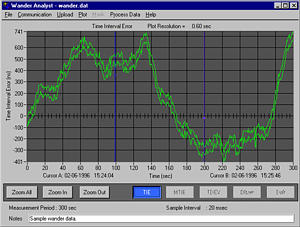
|
||||||||||||||||||||||||||||||||||||||||||||||||||||||||||||||||||||||||||||||||||||||||||||||||||||||||||||||||||||||||||||||||||||||||||||||||||||||||||||||||||||||||||||||||||||||||||||||||||||||||||||||||||||||||||||||||||||
SDH/SONET Compliance TestMTIE and/or TDEV SDH/SONET test specification masks according to: Primary Reference Clock - PRC, ITU-T G.811, and ETS 300 462-6 PRS, GR-2830 CORE Wander generation, Wander output, Phase transient
Slave Clocks - SSU, ITU-T G.812 Type I, ETS 300 462-4 Clock, ITU-T G.812 Type II, Type III Clock, ITU-T G.812 Type IV Clock, ITU-T G.812 Type V, Type VI Clock, GR-1244-CORE Wander generation; Wander tolerance; Noise transfer; Transient response
SDH/SONET Equipment Clock - SEC ITU-T G.813 Opt. 1, ETS 300 462-5 SEC ITU-T G.813 Opt. 2 SMC, GR-253-CORE Wander generation; Wander tolerance; Noise transfer; Transient response
SDH/PDH and Sync Network Interface - SDH and PDH Sync Network, ETS 300 462-3 PRC; SSU; SEC equipment and PDH distribution output SDH and PDH Transport Network, ETSI DEN/TM 3067 2, 34, and 140 MBps output wander
SONET and Sync Network Interface - SONET Sync Network, ANSI T1.101 SONET Network, ANSI T1.105.03 SONET Network, ANSI T1.105.09 DS3 Metallic Interface, T1.404
HDSL Network - HDSL Network, ETS 152 Output wander |
||||||||||||||||||||||||||||||||||||||||||||||||||||||||||||||||||||||||||||||||||||||||||||||||||||||||||||||||||||||||||||||||||||||||||||||||||||||||||||||||||||||||||||||||||||||||||||||||||||||||||||||||||||||||||||||||||||
Real-Time Wander Analyst SoftwareTest Set Requirements - CTS850 Opt. 14 must be installed, System Software Version 2.18 or higher Recommended PC Requirements - Processor: Pentium - Class 90 MHz or faster Operating system: Windows 95/98/NT Memory: 16 MB minimum Hard disk: 2.5 MB + Data Storage
TIE Data Acquisition and Storage - Using RS-232 or GPIB interfaces 50 Hz rate: 1.4 MB/hour 1 Hz rate: 28.8 Kb/hour 0.1 Hz rate: 2.88 Kb/hour Measurement duration: 10 to 109 seconds
Software Processing Functions - MTIE and TDEV calculation: done during TIE data acquisition or postacquisition TIE display: sample or hi/lo envelope Frequency offset and drift rate: in accordance with ANSI T1.101 over a fixed or sliding window with user-definable bandwidth Remove frequency offset (for measurement of RTIE and MRTIE parameters) Graph scaling: automatic or manual, with zoom, cursors Documentation: print, clipboard copy |
||||||||||||||||||||||||||||||||||||||||||||||||||||||||||||||||||||||||||||||||||||||||||||||||||||||||||||||||||||||||||||||||||||||||||||||||||||||||||||||||||||||||||||||||||||||||||||||||||||||||||||||||||||||||||||||||||||
LEDsSDH Status Indicators - LOS, LOF, OOF, LOP, MS-AIS, MS-RDI, AU-AIS, HP-RDI, Signal Present, Pattern Lock, LSS, Error, Pointer Adj
SDH Histograms - Error Count (General), B1, B2, B3, MS-REI, HP-REI, Pattern Bit, Pointer Jitter Defects: On/Off LOS, OOF, LOF, AU-LOP, MS-AIS, HP-RDI, AU-AIS Pattern Loss, Loss of Power Pointers: AU Pointer Value, Pointer Justification
Measurement Utilities - Measurement Control Manual Start/Stop Timed: 1 s to 99 days with 1 s resolution Continuous Histogram Display Resolution High: 1 sec (displays 2 hours with 1 sec resolution) Normal: 1 min, 5 min, 15 min, 1 hour (displays 5 days with 1 min resolution) Low: 15 min, 60 min, 4 hrs, 12 hrs (displays 75 days with 15 min resolution)
Result Logging - All measurements are recorded with start, stop time, and date The current and previous results are stored in memory both totalized and graphical Both graphical and totalized results can be stored on a disk
PDH and TU Status Indicators - TU-AIS PDH AIS LP-RDI PDH RAI
Histograms for PDH and TU - Error Count (General) E1 Defects TU-BIP, LP-REI Pattern Bit, Pointer Jitter
PDH and TU Defects - On/Off LOS, LOF, PDH-AIS, PDH-RAI, TU-LOP, TU-AIS, LP-RDI, TU-LOM, Pattern Loss, Loss of Power
TU Pointers - TU Pointer Value, Pointer Justification UtilitiesTroubleScan - Scans all measurement results for key violations AutoScan - AutoScan to incoming signal (rate, mapping, framing, and pattern) Identifies incoming signal and presents graphical display of AU and TU structure Identifies TU signal status and PDH mux structure by showing TU number, equipped versus unequipped, alarms, and pattern
Stored Setups - 5 front-panel setups in memory 200 front-panel setups per disk
Pass/Fail Tests - Predefined Pass/Fail Tests can be created, stored, and executed Pass/Fail tests are stored on disk 200 Pass/Fail test setups per disk
Add/Drop Interface for - Data Communication Channels and User Channels. A DB-37 female connector provides the interface to an external protocol analyzer. Clock and data signals are differential TTL, conform to V.11 specifications and are also compatible with single-ended TTL signals. Add/Drop: D1-D3, D4-D12, F1, F2, E1, E2 Connector: 37-Pin DIN (DTE and DCE) RJ11-style handset jack for access to E1/E2 bytes
Triggering - Pulse at start of each SDH frame, (Tx and Rx) Connector: 37-Pin DIN
Error Output - B1, B2, B3 bit error selectable Disk Drive - 3.5 inch, 1.44 MB, DOS compatible Measurement Results Stored Setups and Pass/Fail Tests
Printer - Printer support: Epson, HP Thinkjet, ASCII text Serial Printer Port: V.24 Print to disk: BMP format, Interleaf format, Encapsulated PostScript, ASCII text
Computer Interface - IEEE-488.2 interface RS-232-C interface (DB9)
Help Mode - Online task-oriented help Display - 7-inch diagonal CRT, green phosphor Resolution: 640 × 480 pixels VGA output: 15-Pin connector |
||||||||||||||||||||||||||||||||||||||||||||||||||||||||||||||||||||||||||||||||||||||||||||||||||||||||||||||||||||||||||||||||||||||||||||||||||||||||||||||||||||||||||||||||||||||||||||||||||||||||||||||||||||||||||||||||||||
Environmental SpecificationsTemperature - Operating: 0 °C to +40 °C Nonoperating: -40 °C to +70 °C
Altitude - Operating: 4,572 m (15,000 ft.) Nonoperating: 12,192 m (40,000 ft.)
Humidity - Operating: To 95%, relative humidity at or below +40 °C for 2 hours or less To 90%, relative humidity at or below 30 °C, continuous
Transportation Handling - Qualifies under National Safe Transit Association 1s Preshipment Test; 1A-B-1 Physical Characteristics
Power Requirements
|
||||||||||||||||||||||||||||||||||||||||||||||||||||||||||||||||||||||||||||||||||||||||||||||||||||||||||||||||||||||||||||||||||||||||||||||||||||||||||||||||||||||||||||||||||||||||||||||||||||||||||||||||||||||||||||||||||||
Certifications and CompliancesLaser - EN60825 (class 1), 21 CFR 1000 (class I). |
||||||||||||||||||||||||||||||||||||||||||||||||||||||||||||||||||||||||||||||||||||||||||||||||||||||||||||||||||||||||||||||||||||||||||||||||||||||||||||||||||||||||||||||||||||||||||||||||||||||||||||||||||||||||||||||||||||
电话: 010 - 62123258 / 62123259 邮箱: buy17@163.com
- 公司简介
-
 来宝会员
来宝会员
我公司专营全新及二手通用电子仪器仪表设备、测试电缆、测试附件等等。为全国厂商企业、科研单位、各类院校及部队提供质优价廉的仪器仪表。十余年来,以专业细致的技术支持和…... 了解更多>>